Lifting Beams and Spreader Beams : 101

LIFTING BEAMS
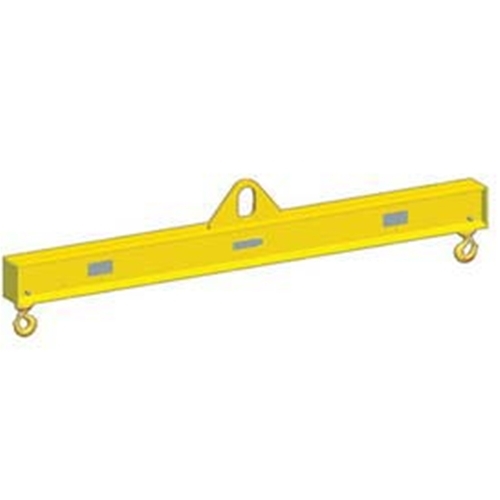
SPREADER BEAM
Lifting beams are designed to be loaded in bending. A simple lifting beam will have an eye or link on the top side to connect to the lifting machine hook and two or more lifting points on the underside to connect to the load. They are ideal for lifting loads which are too weak or flexible to be lifted without support. They are often used when the headroom available is insufficient to accommodate slings.
A spreader is designed to be loaded as a strut in pure compression. The term "Spreader" comes from the original designs which were used to spread the legs of a sling. Typically a simple spreader for a chain sling comprised a bar with forked ends. The forks engaged with the chain and held the bar in place.
Modern spreaders are more sophisticated. Modern spreaders frequently have separate slings connecting to the lifting machine and the load. However the principle remains the same, the spreader is always loaded in pure compression. Spreaders generally need a lot more headroom than a lifting beam in order to accommodate the suspension slings. However, relative to working load and dimensions, spreaders have the advantage of being lighter in weight.
Lifting beams and spreaders can facilitate the lifting of loads not possible by any other means, but there are some limitations to watch out for. Load stability is one major consideration to always keep in mind. With lifting and Rigging slings, the connection to the load is made at or near the top of the load or by wrapping around or passing through the load. This generally means that the connections are above the load's centre of gravity, which should ensure stability. Lifting beams and spreaders enable the connection to the load to be made to the sides or even the base of the load at points below the centre of gravity.
Connecting to the sides or base of a load at points below the center of gravity is desireable for any load with upper parts which might be easily damaged. However caution is required and and you should always follow these guidelines. First, there needs to be at least three connection points. When viewed in plan, the center of gravity must lie within the area bounded by them. When viewed from either side, the load, the lifting beam or spreader and the slings which connect them form four sides of a rectangle.
Another major consideration is load distribution. Whenever a load is supported at several points there is likely to be a degree of inequality in the share of load imposed on each. The likely variation should be taken into account when specifying or selecting the equipment.

In the image above, you can see the various configurations for Lifting & Spreader Beam orientation.

The lifting beam is connected to the skid by four vertical single leg slings. When viewed from the side, the lifting beam, skid and slings form the four sides of a rectangle. Without triangulation the four sides form a mechanism which can deform into the shape of a parallelogram. That is what happens if the load is unstable and starts to topple.
Looked at from the side, the figure above illustrates the situation. The forces which prevent or cause toppling come from the vertical distance from the seat of the lifting machine hook to the sling attachment points on the lifting beam (A) and the distance of the centre of gravity above the attachment points on the skid (B). The centre of gravity will always try to be as far from the hook as possible. If (A) is greater than (B) the arrangement will be stable. The larger the difference, the more stable the arrangement will be. However if (B) is greater than (A), the arrangement will be unstable and will topple. The relationship between dimensions (C) and (D) also affect stability. If (C) is greater than (D) the arrangement will be less stable.